Centrifugal water pumps account for more than 20% of energy use all over the world. Even a little increase in centrifugal pump operating efficiency may result in billions of dollars in savings each year and help reduce carbon dioxide emissions. This study creates a design tool that integrates one-dimensional equations and computational fluid dynamics (CFD) simulations to design centrifugal pump impellers. This examines different combinations of design factors by utilizing both the powerful numerical tools that allow the modeling of numerous scenarios and the large number of empirical equations and coefficients that represent the significant knowledge accumulated in this field. The design tool runs through a series of equations to select the beginning candidates for the different impeller design variables. After that, a design space is established by generating upper and lower bounds for each design variable. The CFD tool executes numerous scenarios inside the design space in order to find the best candidates with the maximum operating efficiency and meet the design objectives. A low specific speed centrifugal pump with a semi-open impeller is used as a case study. The design tool is successful in designing it, fulfilling the design requirement, and increasing operational efficiency when compared to a simple single-arc comparable impeller.

Centrifugal pumps recorded the highest revenue in the water pump market by $30.56 billion in 2021. Due to the global warming problem and the increase in the world population, the centrifugal pump market is expected to increase to $45.56 billion by 2028, presenting a Compound Annual Growth Rate (CAGR) of 5.9% in this period 1 . Water pumps are responsible for over 20% of world energy consumption 2,3 . Therefore, any enhancement in the centrifugal pump operating efficiency, even at a slight rate, saves billions of USD annually and contributes to carbon dioxide emission reduction 3,4,5 .
Centrifugal pumps are designed using empirical data to predict their performance and efficiency as a result of their complex flow phenomena. A flow channel and blade design are then based on experience and coefficients derived from test results 6 . The development of numerical algorithms that can reasonably solve the 3-dimensional Navier-Stokes equations with complex components has been aided by the advent of relatively cheap computers with high processing speeds. As a result, the pump sector also uses Computational Fluid Dynamics (CFD) tools to optimize hydraulic components, improve the accuracy of performance prediction, and consequently save testing costs 7 .
In this work, a design tool that combines one-dimensional and CFD design methods is created. This makes the use of both the extensive knowledge amassed in this area, represented by the vast number of empirical equations and coefficients, as well as the potent numerical tools that enable the simulation of many scenarios to look at various combinations of design factors. To choose the initial candidates for the various impeller design variables, the design tool first executes a set of equations. Then, it creates upper and lower bounds for all design variables to establish a design space. In order to identify the best candidates with the highest operational efficiency and achieve the design goals, the CFD tool performs many situations inside the design space.
As a case study, a centrifugal pump with a semi-open impeller and a low specific speed is used. Compared to a basic single-arc similar impeller, the design tool is successful in designing it, meeting the design requirement, and improving operational efficiency.
The centrifugal impeller design tool consists of two main steps as shown in Fig. 1. First, it runs a 1D model to generate the primary dimensions of the impeller. Second, it performs a 3D CFD analysis to evaluate the performance of the selected model from the previous step. the design tool repeats the second step to fine-tune the model and achieve accurately the required pump performance.
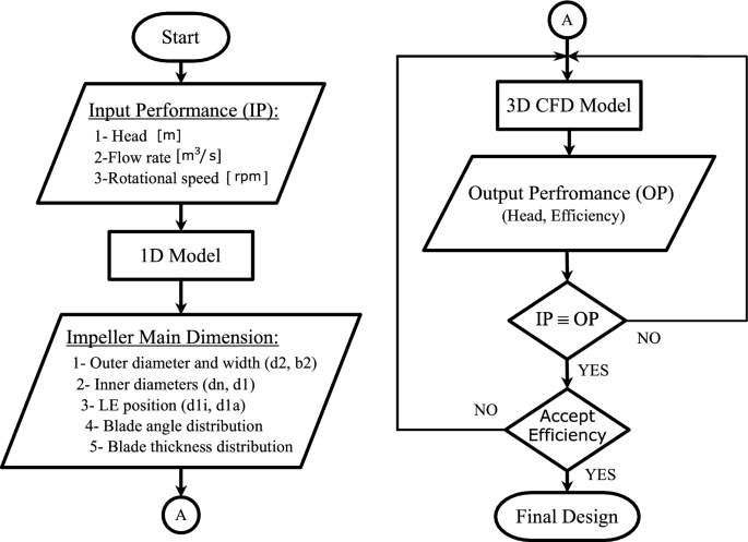
The 1D model consists of a group of equations gathered from different references and the own experience. All these equations are combined and programmed using the open-source high-level programming language Python. The input data for the 1D model is the pump head \(H_ \mathrm \) , flow rate \(Q_ \mathrm <[m^3/s]>\) , and the rotational speed \(n \mathrm <[rpm]>\) at the best efficient point of the pump operation. The 1D model starts by calculating the specific speed \(n_q\) .
$$\beginThen the model estimates the hydraulic \(\eta _\) and total efficiency \(\eta _\) using Eqs. (2–3), respectively.
$$\beginwhere \(Q_\) is the reference flow rate and it equals 1 \(\mathrm \) for \(Q\le 0.005 \ \) \(\mathrm \) .
$$\beginAfter estimating the hydraulic and total efficiency, the volumetric efficiency \(\eta _v\) is calculated from the following equation:
$$\beginwhere \(\eta _m\) is the mechanical efficiency which assumed to be 0.95 in the 1D model. Then, the model calculate the impeller shaft diameter \(d_w\) using the following equation:
$$\beginwhere \(\tau _\) is the allowable shear strength of the shaft material \(\mathrm <[N/m^2]>\) , and \(P_\) is the maximum expected power and is calculated from the following equation:
where \(P_\) is the shaft power consumption at BEP which is calculated from the following equation:
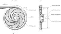
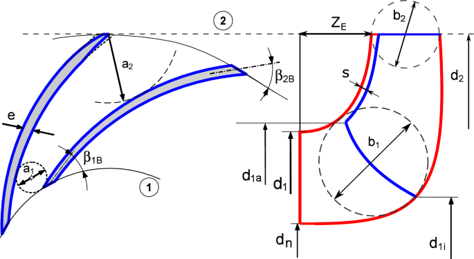
$$\beginIt is frequently necessary to increase the shaft diameter above the minimum that has been calculated based on the torque only by 20:40% based on the shaft size. Then the model starts calculate the impeller blade number \(z_\) and main dimensions: Impeller outlet, inlet, hub diameters \((d_2, d_1, d_n)\) , Leading Edge (LE) hub and shroud diameters \((d_, d_\) , impeller outlet width \((b_2)\) , blade extension \((Z_)\) , blade inlet and outlet angles \((\beta _, \beta _)\) , and the blade thickness (e). The main dimensions of the impeller are represented in Fig. 2.
The head coefficient at the BEP is calculated using the following analytical equation as a function of the specific speed as follows: